Wow, I cannot believe its been a month since my last blog post. I have a lot to tell you about.
Lets start off with a software update. I am currently in the processing of coding a Android Application that will be used to control the robot. I have decided to go with an Android application rather than a full control box because after hours of consideration, I realized that my phone can do everything that the controller box can plus more. It has a speaker, microphone, accelerometer, LCD Screen, 4G network module and antenna, Lithium ion battery that can last up to 9 hours, and its about 100 times smaller than my controller box. So the choice is obvious.
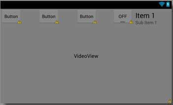
So like I said I am in the process of making the application. I just finished the graphical layout for the buttons. Now I have to program what the buttons do and configure UDP network protocols. I chose to transmit through UDP sockets to ensure reliable communication that won’t get bogged down by lost packets. If I were to use TCP/IP, it would be forced to wait for those dropped packages before it could continue processing newer data. This is doubly bad because old data would be re-transmitted (that's probably for a frame that was already displayed and therefore worthless) and that new data can't arrive until after old data was re-transmitted. The goal is to have as up-to-date information as possible so UDP is the best option.
The Android IDE makes graphical layouts very easy so that didn't take too long. Its mainly drag and drop. Below is an image of what it will look like. It is not set in stone at this point. Changes are ongoing.
Lets start off with a software update. I am currently in the processing of coding a Android Application that will be used to control the robot. I have decided to go with an Android application rather than a full control box because after hours of consideration, I realized that my phone can do everything that the controller box can plus more. It has a speaker, microphone, accelerometer, LCD Screen, 4G network module and antenna, Lithium ion battery that can last up to 9 hours, and its about 100 times smaller than my controller box. So the choice is obvious.
So like I said I am in the process of making the application. I just finished the graphical layout for the buttons. Now I have to program what the buttons do and configure UDP network protocols. I chose to transmit through UDP sockets to ensure reliable communication that won’t get bogged down by lost packets. If I were to use TCP/IP, it would be forced to wait for those dropped packages before it could continue processing newer data. This is doubly bad because old data would be re-transmitted (that's probably for a frame that was already displayed and therefore worthless) and that new data can't arrive until after old data was re-transmitted. The goal is to have as up-to-date information as possible so UDP is the best option.
The Android IDE makes graphical layouts very easy so that didn't take too long. Its mainly drag and drop. Below is an image of what it will look like. It is not set in stone at this point. Changes are ongoing.
I am also working on testing each individual electrical system via the Beaglebone's GPIO and deriving the equations needed to convert sensor voltage output to useful data. This was actually the first time I had booted up the Beaglebone so I had to go through the process of uploading the Angstrom operating system to the EMMC internal memory on the BBB. I plugged in my Ethernet cord, set up an SSH connection through Putty, then installed the Adafruit's python library and was ready to
Once I started testing, there was a problem. When I sent a HIGH signal to the MOSFET, the fan jittered, but didn't even have enough power to make one full revolution. It was evident that there was either low voltage being supplied or not enough current. Well I checked it with my multimeter and noticed that the MOSFET was only supplying 2v to the fan rather than 12v! I was confused how this was happening so I performed multiple experiments with different resistor configurations and loads to see if that affected the transistor switching. No results. It turns out that the Vgs (gate threshold voltage) for that particular transistor (IRFZ14PBF) was 4v and the BBB GPIO can only output 3.3v! So I ordered some new MOSFETs that have a lower Vgs around 2v. That should fix it.
Once I started testing, there was a problem. When I sent a HIGH signal to the MOSFET, the fan jittered, but didn't even have enough power to make one full revolution. It was evident that there was either low voltage being supplied or not enough current. Well I checked it with my multimeter and noticed that the MOSFET was only supplying 2v to the fan rather than 12v! I was confused how this was happening so I performed multiple experiments with different resistor configurations and loads to see if that affected the transistor switching. No results. It turns out that the Vgs (gate threshold voltage) for that particular transistor (IRFZ14PBF) was 4v and the BBB GPIO can only output 3.3v! So I ordered some new MOSFETs that have a lower Vgs around 2v. That should fix it.
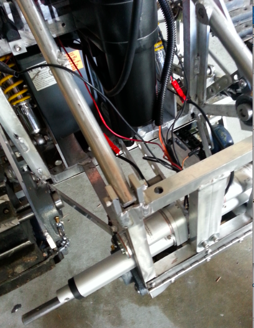
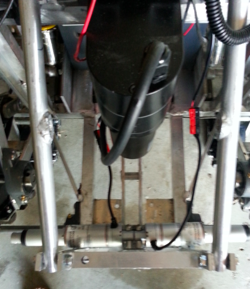
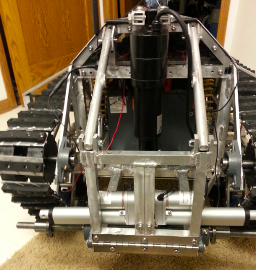
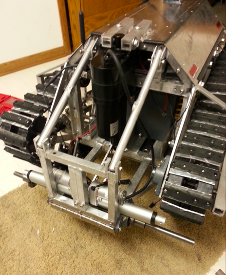
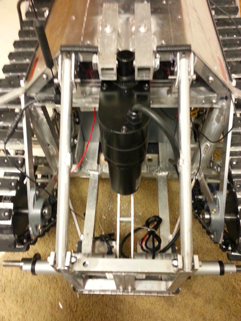
| I also finally received the linear actuators in the mail and as you can see in the images on the right, they look awesome. I performed some tests using my DC power supply and they function as hoped (in regards to speed and power). I installed them without any issues. So now I just have to get the extractor forks fabricated. They do require a bit of redesign. This is a tricky part because when they are not in use, they need to be folded towards the robot so there aren't these long forks hanging off the back that could hit something when the robot is running. So I need to design a system that can fold the forks when in the UP position, but will not obstruct the fork from sliding under a victim's shoulder. Tricky indeed. I'll figure it out and let you know of my solution. Going to think outside the box and have to get creative here. | |


Future Work
1) Fabricate extraction forks
2) Solder replacement transistors and get all sensors and other devices functioning individually
3) Get the VES System functioning
4) Weld support on doglegs to prevent bending
5) Program Android application
6) Replace 3/4" wide track pads with 1.5" wide track pads
7) Purchase new shock absorbers
 RSS Feed